RGB LED Module with DMX512 Interface
tiny 3-channel DMX-Receiver using PIC Microcontroller
This project is a low cost 3-channel DMX-Receiver for a single RGB LED using a very tiny and cheap PIC microcontroller.
 Aim of this circuit is to control a single RGB-LED ( package: SMD PLCC6 ) using DMX512 protocol with the at least possible material cost. For cost reason the module uses only one data line to receive DMX512 data, this is also know as DMX single ended. By this the modules can be connected using only three lines ( 5V, GND, +data DMX512).
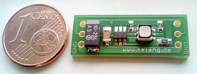
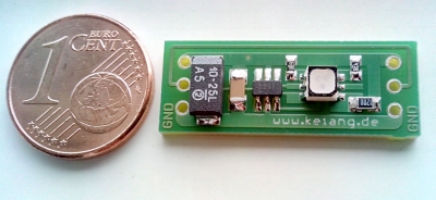
The complete circuit is made with only seven parts, overall material costs inclusive the PCB (single sided) and the RGB LED are about € 1.00 - € 3.00 (depending on LED and quantity). The PCB has the dimensions of 10.0 x 26.5 mm and is designed to be interconnected as array. It is controlled by the popular DMX512 protocol and provides for each LED 16.7 million colors.
The core of the circuit is a low cost PIC10F222 microcontroller from Microchip, which is already available at a price of about 40 cents. Due to its port I/O architecture, the microcontroller can easily deliver 20mA per port pin and thus control a RGB LED directly. A 3-channel PWM modulation and DMX512 protocol is implemented in software (assembler).
The PWM modulation operates at a frequency of:
Software
Gamma correction
Modules do not make use of a gamma correction. Light output is strict linear to DMX512 data. In case a gamma correction is needed it has to be done in DMX512 Master (or PC Software) and gamma corrected values can be send to Modules.
DMX512 address
Unlike standard DMX512 devices in this module, due to cost and space limitations, the DMX address of the slave is not adjustable with switches. The DMX512 address is stored in the flash memory of the microcontroller and can be customized with the Microchip ICSP Flash interface. This can normally done when flashing firmware into microcontroller and is even possible when microcontroller is soldered to PCB. Microcontroller don't need to be removed from PCB for changing DMX-Address, this can be done in circuit.
The microcontroller performs the following tasks:
- synchronize to the DMX512 protocol (wait for start-up sequence)
- listen to the DMX512 bus and wait for valid address, save the received data in RAM
- from the received DMX512 data generate a 3-channel PWM signal for driving RGB LED
- if LEDs switched off and more than 3 minutes no activity on the data bus is detected then go into standby
RGB LED
For this module i used the RGB LED "LRTB G6TG" from OSRAM. With a corresponding adjustment of the resistors, other LEDs with PLCC6 package can be used too. The LED has a viewing angle of 120° and a very good color mixing because of a diffused silicone resin. Due to the relatively high optical efficiency it delivers at 20mA an adequate brightness for the planned application (TV Ambient-Light).
optical efficiency (taken from datasheet):
- red: 43 lm/W
- true green: 36 lm/W
- blue: 11 lm/W
Power Consumption
Complete circuit needs in normal operation round 1mA at 5V (excluding LED). If more than 3 minutes, no activity is detected on the data bus and the LED is off then microcontroller goes into standby mode to reduce the power consumption to 1µA. It will automatically awake at any activity on data bus und go back to normal operation. This feature allows the module even in battery-powered applications to use with long standby time, without the power supply of the modules must be switched off.
The LED is operated with a maximum current of 20 mA per color and controlled with PWM technology for a lossless dimming.
The maximum power consumption of a module is:
( current microcontroller etc. + LED current * 3 ) * supply voltage = (0,001A + 3 * 0,02A) * 5V = 0,305W.
In standby mode the overall module power consumption is only: 1µA * 5V = 5µW !
Hardware
block diagram: LED-Nanoit
schematic: LED-Nanoit
dimension of module LED_Nanoit
PCB (single sided) LED_Nanoit
assembled PCB LED-Nanoit
LED Module connected in array
component list
| Part | Value | Short description | Quantity | ordner number (german electronic distributor: www.reichelt.de) |
|---|---|---|---|---|
| C1 | 100nF | SMD-Ceramic-Capacitor, 100N, 10%, X7R | 1 | X7R-G1206 100N |
| C2 | 10µF | SMD-Tantal-Capacitor, 10µF/16V, SMC_C | 1 | SMD TAN.10/16 |
| IC1 | PIC10F222 | Microchip PIC-Controller, SOT-23-6 | 1 | PIC 10F222T-I/OT |
| R1 | 47R | SMD-Resistor, 0603, 47 Ohm, 1% | 1 | SMD-0603 47 |
| R2 | 120R | SMD-Resistor, 0805, 120 Ohm, 1% | 1 | SMD-0805 120 |
| R3 | 68R | SMD-Resistor, 0603, 68 Ohm, 1% | 1 | SMD-0603 68 |
| LED1 | LRTB G6TG | OSRAM 6-lead MultiLED, PLCC6 | 1 | LRTB G6TG |
| Reichelt Shopping Cart: "LED_Nanoit" | ||||
some demo videos
using 50 RGB LEDs modules controlled via DMX512 protocol
using 15 RGB LEDs modules controlled via DMX512 protocol
using 6 RGB LEDs modules controlled via DMX512 protocol
KeiAng
Publiziert am: Freitag, 16. September 2016 (33416 mal gelesen)
Copyright © by Keiang''s electronics hobby side
[ Zurück ]